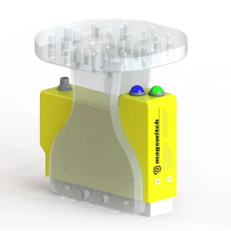
COBOT Magbase 10 2.0

Description

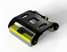
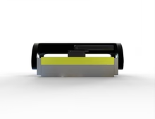
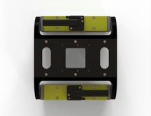
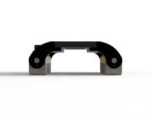
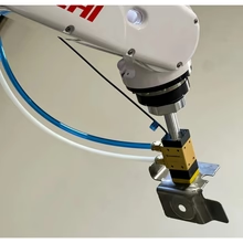
Magswitch arrays can be anchored flat or pivoted to allow mounting to cylindrical ferromagnetic surfaces and feature a wide footprint to reduce the risk of peel and pry when the end effector is at its greatest radius. Refer to the dimensional drawing below. The standard mounting plate is ready for mounting FANUC CRX-10, UR10, and UR16 COBOTS. Custom mounting plate and patterns can be incorporated; contact us for more information about customization.

This replaces MagBase 10 Product # 81001289.

Consult our Applications Team for help with sizing for COBOT applications as we will consider payload, reach, mounting surface and attitude.

SPECIFICATIONS

Nominal Maximum Breakaway Force1,2,4  22072 N
Nominal Maximum Shear 1,2,4 4846 N
Full Saturation Thickness  0.5 in / 12.7 mm
Net Weight  66 lbs / 30 kg
Individual Magnetic Pole Footprint 2.8″ x 11.7″ / 71mm x 296mm
Overall Footprint 5.6″x14.8″x15.6″ / 143mm x 376mm x 396mm


The following is maximum magnetic force “breakaway” data for ONE swivelling magnet array. There are TWO installed on each Cobot Magnet Base. Consult operation manual 1101424 for more information.

Material Thickness – mm (in) 1.5 (.059) 1.9  (.075) 2.7 (.106) 3 (.118) 3.5 (.138) 4.76 (.187) 6.35 (.250) 9.53 (0.375) 12.7 (0.500) 19.05 (0.750)
Max Force 1,2,4 -N 1585 2109 3503 3648 4058 5591 8626 10241 10712 11036


1:  Determined in a laboratory environment on 2” thick SAE1018 Steel with a surface roughness of 63 micro inches with optimized pole shoes. Many factors contribute to the actual breakaway force and safe working load in each application. Consult a Magswitch Applications Engineer and test the Magswitch in each application before deployment.
2:  All data applies to units with flat pole shoes installed.
3:  Values may vary by +/- 5%.
4:  Maximum forces listed above are not safe lifting forces. Designers must take into account safety factors when specifying tools. Magswitch recommends SWL = 5:1 for most applications.