Magwing 10

Description

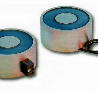
Pairs of MagWings can be anchored flat or pivoted to allow mounting to cylindrical ferromagnetic surfaces. Customers can design their own bases for the MagWing to mount drills, COBOTs, or other tools to make work faster, safer and easier. Included hardware (M8x1.25 screws and two 8mm dowel pins) should be used to attach custom bases to MagWings. Refer to the dimensional drawing below for fastener locations or consult our Applications Team for help with sizing for COBOT applications as we will consider payload, reach, mounting surface and attitude.

Sold as individual units, most applications require two or more MagWings.

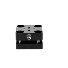
Custom mounting plate, bolt and dowel patterns can be incorporated. Contact us for more information
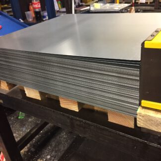
Material Thickness – mm (in) 1.5 (.059) 1.9 (.075) 2.7 (.106) 3 (.118) 3.5 (.138) 4.76 (.187) 6.35 (.250) 9.53 (0.375) 12.7 (0.500) 19.05 (0.750)
Max Force – N 1585 2109 3503 3648 4058 5591 8626 10241 10712 11036


Max Breakaway Force 161 lb / 73 kg
Max Shear Force 38.8 lb / 17.6 kg
Min Thickness for de-stack 0.197 in / 5.0 mm
Max Allowable Pressure 90 psi / 0.62 MPa
Min Actuation Pressure 21.76 psi / 1.5 bar
Max Actuation Pressure 89.92 psi / 6.2 bar
Net Weight 1.33 lb / 605 g
Air Port thread 2x G1/8
Mounting options Top: Ø8-M8-Ø8-M8 Side: 2x Ø6-M8-Ø6
Magnetic Pole Footprint 54 x 31 mm

* Max Breakaway determined in laboratory environment on 2” thick SAE1018 Steel with surface roughness 63 micro inches. Many factors contribute to the actual breakaway force in each application. Always test the magswitch in each application before deployment. Refer to the magswitch information booklet for more information.

  • SWL (Safe Working Load) = Maximum Force5/ Safety Force (≥5)
  • 1Determined in laboratory environment on 2” thick SAE1018 Steel with surface roughness 63 micro inches with optimized pole shoes. Many factors contribute to the actual breakaway force and safe working load in each application. Consult a Magswitch Applications Engineer and test the Magswitch in each application before deployment.
  • 2All data applies to unit with flat pole shoes installed.
  • 3Determined with SAE1018 Steel L=200mm W=200mm.
  • 4Values may vary by +/- 5%.
  • 5Maximum forces listed above are not safe lifting forces. Designer must take into account safety factor when specifying tool. Magswitch recommends SWL = 5:1 for most applications.